How to make a Sine Bar (and why you really should…!)
I have a need to mark out some angles very accurately and precisely, more precisely than the 1º that is marked on my protractor – and even that is struggle to see, these days. Fortunately there is a tried and tested way of getting angles to a very high degree of precision, accurately, in the workshop. We may not be able to measure angles to one decimal place, but it is easy to measure lengths so.
Cast you mind back to when you were at school. Were you the kid at the back writing on the desk, or were you paying attention? I hope it was the latter, because we are going to use Sines. You will remember that the Sine of an angle is the sideways displacement of a rotated unit length. At 0º there is no sideways displacement (sin0 = 0) and at 90º there is total sideways displacement (sin90 = 1). All angles in between are between those two limits, so, for example, sin30 = 0.5, sin45 = 0.707.
We can find a table of sines in any engineering handbook. Over here in the UK we have the Zeus book, found in every workshop. I'm sure that there is the equivalent where you live. As well as the Table of Sines, we also need a Sine Bar.
Start by obtaining your anvils. These are a pair of short, fat, cylinders. Mine are 20mm diameter and 20mm long brass. My friend Stuart made them for me. It does not matter what size they are, but:
They must be the same diameter
You must know what that diameter is
You must have a drill to match
You must also know the distance between the holes. In my case, I am working in Inches and the distance between the holes is 10”, simply because multiplying a sine value by 10 is very easy. If you are not comfortable using Inches, and want to work solely in mm, then choose something like 200 or 250mm. The bigger the sine bar, the more accurate it will be.
How do we drill two holes 10” so precisely? Well I made a 10” spacer as carefully as I could, set a stop on my drill press and drilled one hole, then inserted the spacer to drill the second. That way the holes were 10” apart as accurately as I could determine.

Shotting to a 10” length

It has to be as exact as possible
With a stop set on my drill press, I can use the spacer to drill two holes exactly 10” apart.

Drill the first hole against a stop…

…and the second hole with the spacer against the same stop
Then there is a bit of bandsaw work to do, to create a bit of clearance. The absolute shape is not important. When cleaned up, the anvils are glued in with epoxy resin.


Finally we have to trim the working edge, and this is a bit tricky, so I make sure that my tablesaw has its guard adjusted properly, because it entails getting my fingers closer to the blade than I would normally feel comfortable with.
With the anvils riding against the rip fence, skim the edge of the sine bar. This ensures that the working edge is exactly parallel to the cotangent of the anvil. A coat or two of lacquer and it is finished.


Now we need a spacer. In my example I need to set up 6.7º, so we find the sine of 6.7. which is 0.117. This is then multiplied by the distance between the anvils (which is why I chose 10”) which gives me 1.17”. If your Sine Bar is, say, 200mm, you will have to multiply 0.117 x 200, which is 23.35mm.
To make a spacer this long we cut it a tad oversize and then use a shooting board to bring it down to length, measuring with each pass with a digital vernier gauge. If you are not comfortable shooting such a short length, plane a length of stock down to thickness and use it on its side instead.

Shooting the spacer

Perfect!
There are two common scenarios where I use a sine bar in my workshop. The first is to set the mitre fence of my tablesaw.
Start by fixing two pairs of folding wedges in the mitre track of your TS and hold a roofing square against them to give a reference edge straight across the bed. Then set up the sine bar with the spacer underneath one anvil and set the fence to that. It will be accurately 6.7º. By flipping the arrangement over, it can be made to read exactly 6.7º in the opposite direction too.
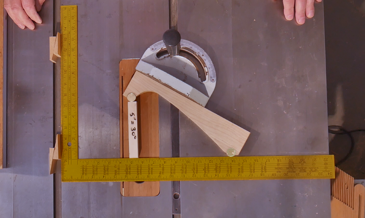
Setting mitre fence - note the clearance behind the lower anvil so that it doesn’t catch on the reference surface
The other common situation is to set up my sliding bevel. I set up the sine bar and spacer against the fence of my shooting board and then set my sliding bevel to that.

This is all very quick and easy, but it is precise and accurate, and it doesn't break the bank. You can see mine on YouTube
Enjoy!